 Install an Atari 8 Bit into a PC Case
This is a project where I put an Atari 130xe in a PC Tower Case.
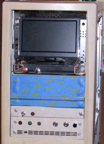
Scope of Hardware to install An Atari 8 Bit inside a PC Tower Case.
[X] Build Switchable Multiplexer Cartridge to Swap from Master to Slave 8.
[X] ECI to PBI Expansion Board with Dual Cartridge Ports.
[X] Mount AtariMax USB SIO2PC and bring LED's to front panel.
[X] install and test Atari 8 Bit Stereo dual pokey Audio Board.
[X ] VBXE 2.1 need to Install Lotharek web site
[X] Built Power Connector to plug into Towers Molex Power connector
[X] 9 Pin Male and female ribbon cable connectors to make extension for Joystick.
[X] Mounting Hardware, LED, and Switches
[X] This work is complete
[ ] Work that still need to be done.
When Installing an Atari into a PC Tower Case it is most important to use extension cables instead of cutting and Splicing the PC Tower Power Supply. Doing this upgrade this way should the PC Tower Power supply fail it is very easy to replace a power supply failure.
Standard Atari 130xe brand new out of the Box
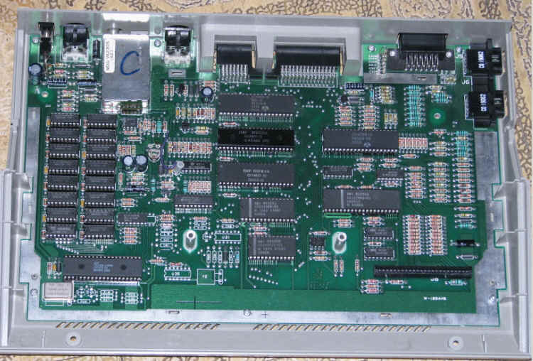
This 130xe is the only one I have ever found to be socket fresh out of the box from the Atari Corp. I ran this computer on self test for one week 24/7. Now that it passed all the burn in tests it is ready to be upgraded with the Ultimate 1 Meg upgrade that I purchased from Lotharek this was an easy upgrade that does not require removing any dram chips. the upgrade requires only removing two chips and 4 solder joints to be made. Here are the directions for upgrading a 130xe with the ultimate 1 meg.
65XE/130XE
I also installed my AKI Keyboard interface since this Atari Board will end up in a pc tower case.
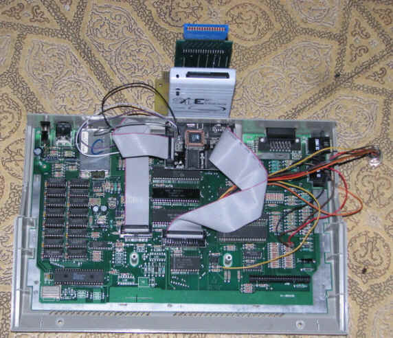
I flashed the Ultimate 1 Meg with a version of SpartaDos X that works with the Multiplexer. So as I prepare the PC Tower case to accept the Atari hardware this machine is running my Multiplexer master software. I still need to add a few switches for Multiplexer bypass, a switch to swap the Master into a slave, a switch to bring up my memory monitor within the Multiplexer OS. I also need to install my Stereo Pokey board.
Here is the Stereo Pokey Board that I need to install.
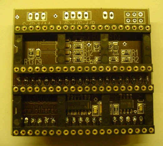
Here is my AKI keyboard interface installed in a 130xe.
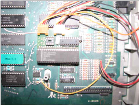
I will have to stack the Stereo Pokey board on top of my AKI Keyboard interface since both need the Pokey chip in it's normal location.
Internal TFT LCD Monitor Build.
Since this Atari will end up being my Multiplexer master I decided to put a small Monitor into the bays of the PC Tower case so I can at a glance see if the Multiplexer Master is up and running. I ordered a 3 1/2 inch LCD backup monitor that is used in cars. I build the insert out of lexsand and a 3 1/5 to 5 1/4 hard drive housing.
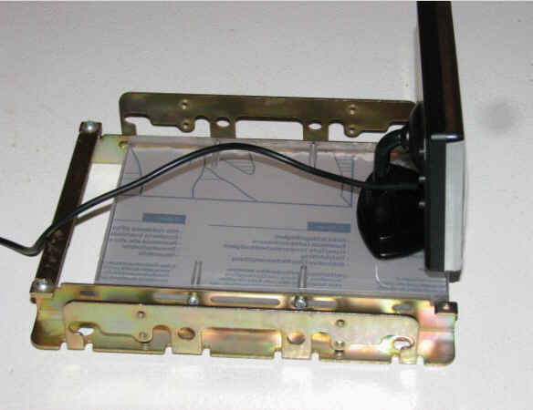
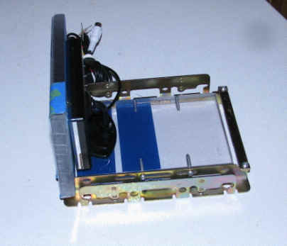
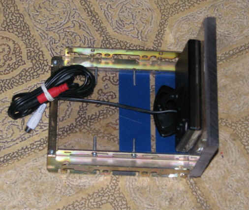
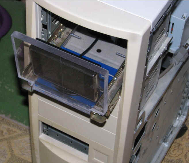
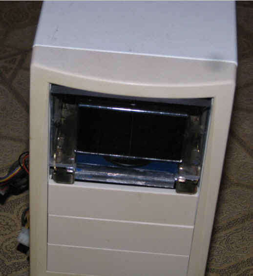
Preparing the PC Tower case to accept the modified 130xe with all to upgrades.
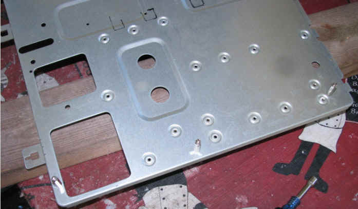
I used a broken 130xe to prepare the PC tower case. If you decide to do a build like this use a broken 130xe to do your measurements this will make sure you do not get any metal filling in your working Atari Computer.
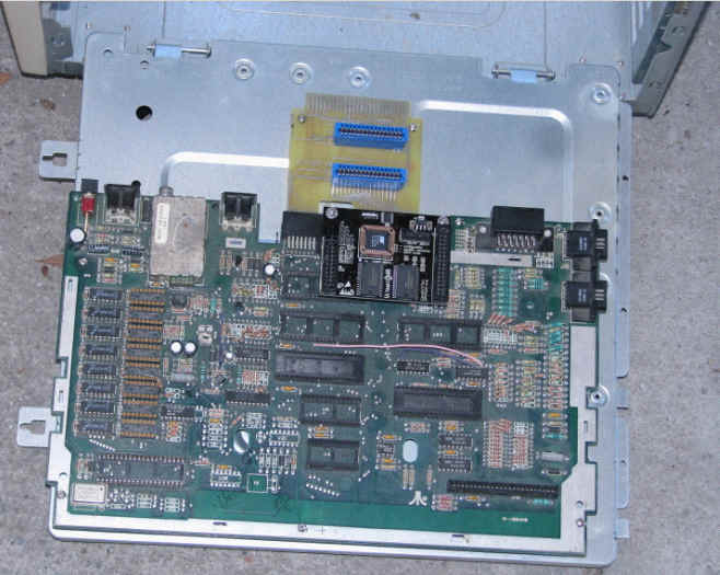
Here is how the mother board fits along with the expansion board to hold the Side 2 and Multiplexer Cartridges.
Multiplexer Bridging Cable This PC blank off fits the PC Tower Cage and bring the 34 pin Ribbon cable in to attach to the Multiplexer. This ribbon extension is about 12 inches long and has a 34 pin connector on the other end not showed in this picture. I trimmed the PC blank off so that the ribbon cable would not be pinched.
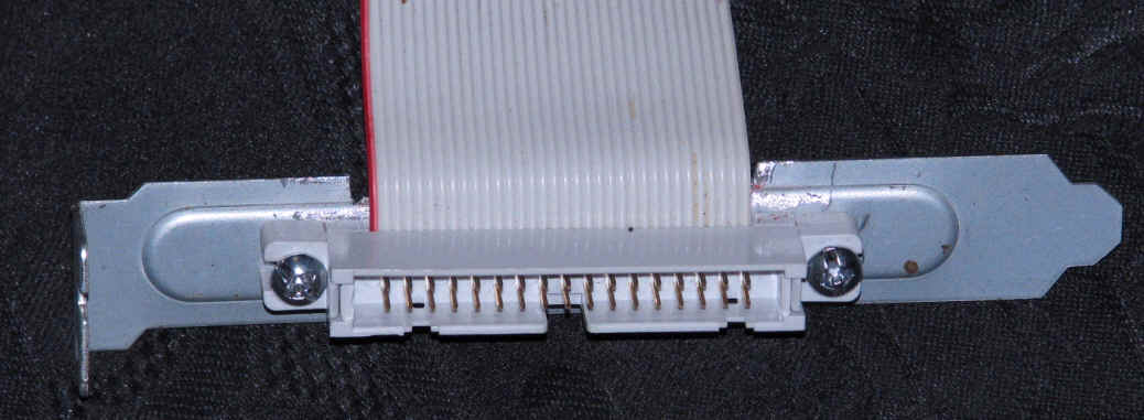
Here is a better picture to see what I am doing. This will allow me to plug this computer into the Multiplexer buss without having to have a bunch of cables coming out the side of the PC tower Case. This is a 34 pin Bulk Head connector. It crimps onto the ribbon cable and then you can mount the connector so that it stays put.
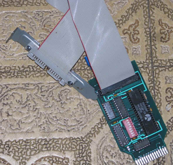
NTSC Video and Audio Output hookup ports. This is the standard external hookup for NTSC Video and Audio output
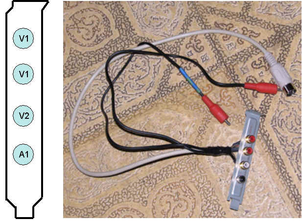
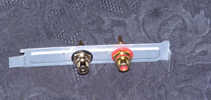
RCA Jacks V1 is Standard NTSC video Composite Output.
RCA Jack V2 allows you to feed NTSC Composite video onto the internal Monitor
RCA Jack A1 is the audio output to feed a normal NTSC composite Monitor.
Because my internal LCD TFT Color Monitor is shows normal NTSC/PAL Video except for when you put the car in reverse it takes a video feed from the backup camera. This extra port can be useful if you need to check something real quick. The internal monitor that is installed in the PC Tower Case is for reference. It would be very hard to program from the 5 in LCD Monitor. I put this into this project because I use a Multiplexer that allows me to tie 8 Atari Slaves to a single master having reference monitors even small lets me know all is well with my Multiplexer System.
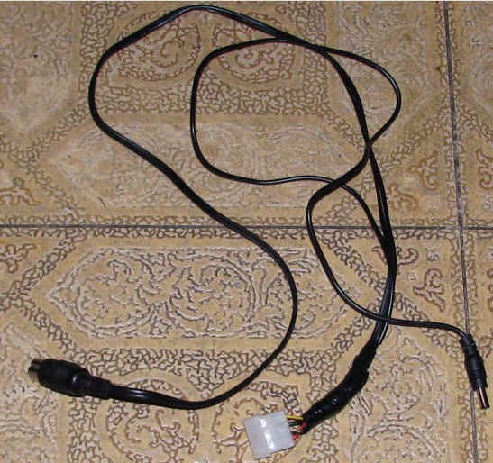
Power supply Cable t power both the 5 volts and 12 volts that are needed.
I just use an PC Extension cable and pull the 5 volts to feed the Atari and 12 Volts to provide power for the internal LCD TFT NTSC/PAL monitor. The I just plug the cable up just as if I was hooking up a Hard disk or CD-ROM. By using extension cables I can change the power supply in just a few min's if I need to. I got the Atari Power supply cable from an Atari Power Supply that went bad.
Stereo Pokey output Port. Took a PC tower Blank off and mounted the RCA output ports to them.
I added an LM386 Speaker amp Board I found on e-bay. it added a real nice speaker to the Atari Tower.

Construction of Joy Stick Extension cables.
Here are male and female 9 pin Ribbon Cable Connectors which is how I am going to bring the Joy Stick Port to the outside the PC Tower Case.
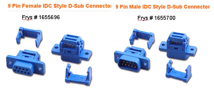
These have been built and tested and installed into the PC tower case. In the RealDos Construction set is a program call Porttest.com that you can use with a joy stick to test extension cables before installing them.

These 9 pin extension cables were installed into the tower case in this manor.
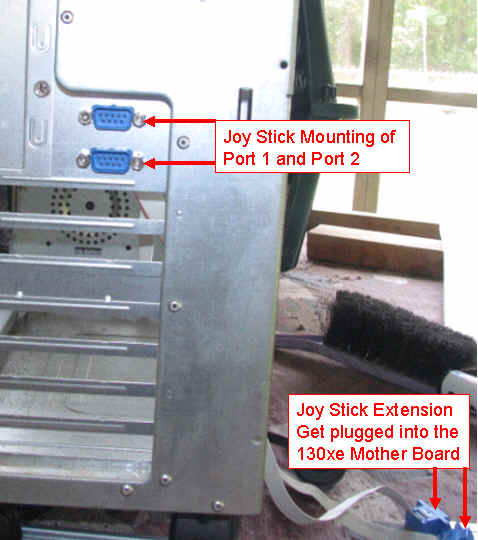
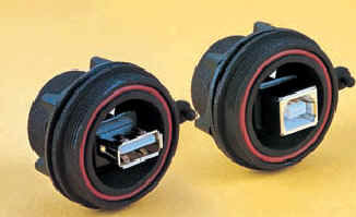
I have ordered USB Bulk head connectors for the USB Connections that will be needed for the AtariMax SIO2PC.
Here is a picture of the bulkhead connectors I ordered for this project.
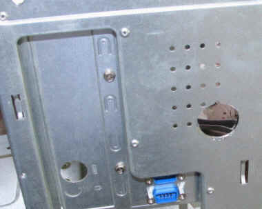
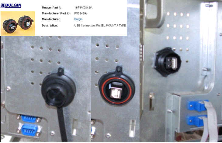
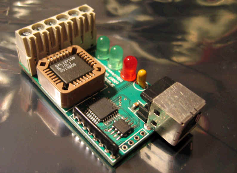
Here is the SIO2PC that will be installed inside the PC Tower Case.
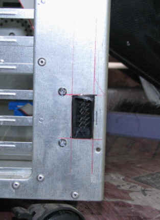
Here I have cut and prepped a location to mount a 13 Pin Atari Serial Port. This port has all 13 wires.
